Three-way globe valves
 |
 |
|
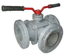
Flanged |
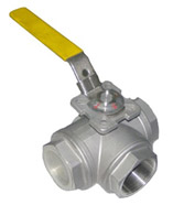
Trunnion-mounted |
PURPOSE AND SCOPE
Three-way globe valves are used as locking and locking-controlling arms of industrial pipelines in different industries. Valves operating mediums are natural and liquefied gas, oil products, water, carbon dioxide and other mediums, which are neutral to valve materials.
ADVANTAGES AND DETAILS OF CONSTRUCTION:
- globe valves have full-bore construction and are made in the version with manual drive;
- valve construction is modular, it consists of one-piece body and three or more joints connected with body by stud bolts that provides its maintainability;
- depending on the operating conditions three-way globe valves are made with L- or T-shaped pass on the plug (globe);
- valve operation scheme (supply and overlapping of operating medium in all positions of the locking device) are agreed while ordering;
- globe valves are made with manual (mechanical) drive, with pneumatic and electric drive.
Technical Characteristics
| Hermiticity class according to GOST9544 | Class A | |
| Climatic version according to GOST 15150-69 | U1 - moderate (surrounding temperature from -45ºС to +50ºС)HL1 - cold (surrounding temperature from -60ºС to +40ºС) | |
| Type of control | R - manual (mechanical) drive | |
| Joining to pipeline | Flanged according to GOST12815-80 Trunnion-mounted according to GOST6527-68 |
|
| Total average service life | Not less than 8 000 cycles | |
| Total average life | Not less than 1 500 cycles | |
| Valve shape | L-shaped, T-shaped | |
| Operating medium | For material version - C | water, air, oil, vegetable oils and industrial oils, petroleum, diesel, kerosene, gasoline, natural and liquefied gas, oil, water, carbon dioxide |
| For material version – Н or М | corrosive fluids (acids and alkalis), gases containing aggressive impurities (hydrogen, oxygen, sulfur, hydrogen sulfide, etc.), etc. | |
| Manufacture | Serial according to TU U 29.1-35907383-001:2008 | |
Material category*
| Main parts | Material | ||
| C | H | M | |
| Body | Steel 20 | Steel 12X18H10T | Steel 10X17H13M2T |
| Flange | Steel 20 | Steel 12X18H10T | Steel 10X17H13M2T |
| Ball | Steel 30X13 | Steel 12X18H10T+Xtv30 | Steel 10X17H13M2T+Xtv30 |
| Seat | Fluoroplastic F-4 | ||
| Spindle | Steel 30X13 | Steel 12X18H10T | Steel 10X17H13M2T |
| Packing box | Steel 20 | Steel 12X18H10T | Steel 10X17H13M2T |
| Sealing | Fluoroplastic F-4 | ||
Main dimensions and drawings
 |
|
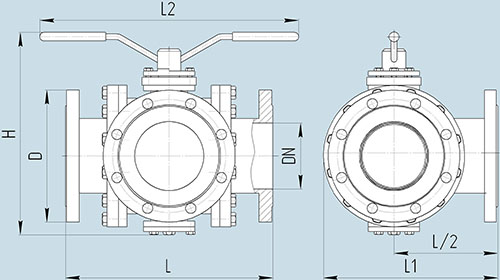
Three-way globe valve flanged
|
 |
|
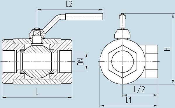
Three-way globe valve trunnion-mounted
|
Basic globe valve versions. Scheme of conventional symbols
| Valve model | Diameter DN, mm | Nominal pressure PN, MPa (kgf/cm2) | Material | Drive type | Connection to the pipeline | Climatic version | Overall dimentions mm | Weight, kg | ||||
| L | L1 | L2 | H | D | ||||||||
| THR | 25 | 0,6 (6) 1,0 (10) 1,6 (16) 2,5 (25) 4,0 (40) |
C H M |
R | Flanged | U1 HL1 |
180 | 150 | 310 | 190 | 115 | 8,0 |
| 32 | R | 200 | 170 | 320 | 200 | 135 | 12,0 | |||||
| 40 | R | 200 | 175 | 380 | 210 | 145 | 16,0 | |||||
| 50 | R | 230 | 195 | 385 | 220 | 160 | 18,0 | |||||
| 80 | R | 300 | 240 | 480 | 250 | 195 | 28,0 | |||||
| 100 | R | 350 | 280 | 500 | 290 | 215 | 42,0 | |||||
| 150 | R | 400 | 350 | 620 | 390 | 280 | 78,0 | |||||
| 200 | R | 400 | 350 | 620 | 390 | 280 | 78,0 | |||||
| 10 | R | Trunnion-mounted | 68 | 51 | 106 | 58 | - | 0,4 | ||||
| 15 | R | 75 | 57 | 138 | 61 | - | 0,55 | |||||
| 20 | R | 86 | 65 | 138 | 74 | - | 0,8 | |||||
| 25 | R | 103 | 78 | 162 | 81 | - | 1,5 | |||||
| 32 | R | 115 | 86 | 162 | 88 | - | 2,2 | |||||
| 40 | R | 125 | 94 | 220 | 104 | - | 3,3 | |||||
| 50 | R | 146 | 110 | 220 | 110 | - | 4,3 | |||||
Example of conventional symbol at the time of order
Three-way globe valve flanged model THR with nominal diameter DN50 and nominal pressure PN2,5MPa, valve material carbon steel 09G2C, manual drive, climatic version HL1, T-shaped, operating medium - nitrogen up to +180ºС.
Valve THR-050-025-С-R (flanged, HL1, T-shaped, nitrogen up to +180ºС) TU U 29.1-35907383-001:2008
Notes:
1. Joining type, climatic version, requirements for compliment of pneumatic and electric drives, peculiarities of operating medium are named in brackets after main description of a valve.
2. To order valves with parameters which are different from ones shown in the table please fill in check list and send to us, so we can confirm our ability to meet your requirements.

